
- Hyuga -
INJ Hyuga – Tyler
5.5 units, 26 seconds, Japanese battleship
The Ise/Hyuga were built as
improvements on the design of the Fuso/Yamashiro battleships and were completed
in the late 1910’s. They similarly featured 6 turrets each with two 14 inch
guns which was theorized to have advantages in the amount of total projectiles
per minute the ship could fire broadside with additional advantages of each
having independent fire control as such to get a higher number of shots on
target sooner and keep a higher number of guns firing in the event of the loss
of a turret in combat. The flaw was that in reality the center turrets had
limited firing arcs and also that there were multiple magazines spread out
throughout the ship making protection more challenging. The successor
battleship in the Japanese Navy was the Nagato, which was the first ship in the
world to mount 16 inch main guns and they were placed two each in 4 turrets in
in sets right next to each other making it more possible to concentrate the
protection. The ships were heavily upgraded during the 1930’s adding armor
bulging and length as well as substantial superstructure changes. The two ships
were again heavily modified after the battle of Midway to include posterior
flight decks as the stern most 2 turrets were removed as a response to
significant aircraft carrier loss.
Both the Fuso and Ise class are interesting ships in
out hobby because of several advantageous design features. The multiple turrets
allow for several options for gun placement including the option of creating a
very dangerous stern. The ships have two twin rudders and four shafts. Also,
they have a heavy amount of casemate guns for protection against stern guns
amidships. The disadvantages are that they are 26 second ships that are about
as large as a ship can be before it reaches the threshold for 24 seconds.
Additionally they are 5.5 units rather than 6 making the choice of a 2 pump
setup less seamless, and the smaller class 5 rudders in a ship otherwise Nagato
size means a favorable turning radius can be more difficult to achieve.
I received this boat in a state of refit. It was a
wood hull ship. The original builder had done a fairly OK job with certain
parts of the wood work but other aspects were less ideal. Also, concrete sealer
was filled between the ribs for water channeling instead of something lighter
like balsa which has been my preferred method. This article will document the
rebuilding process.
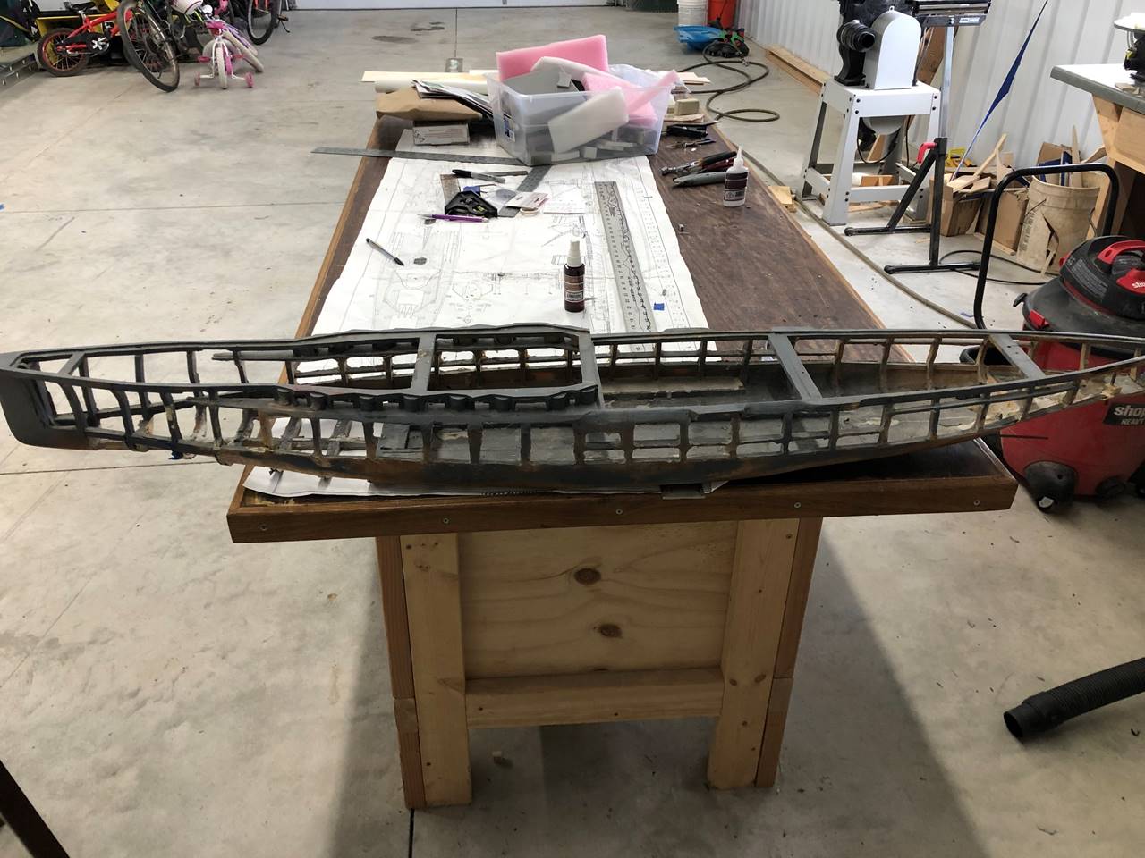
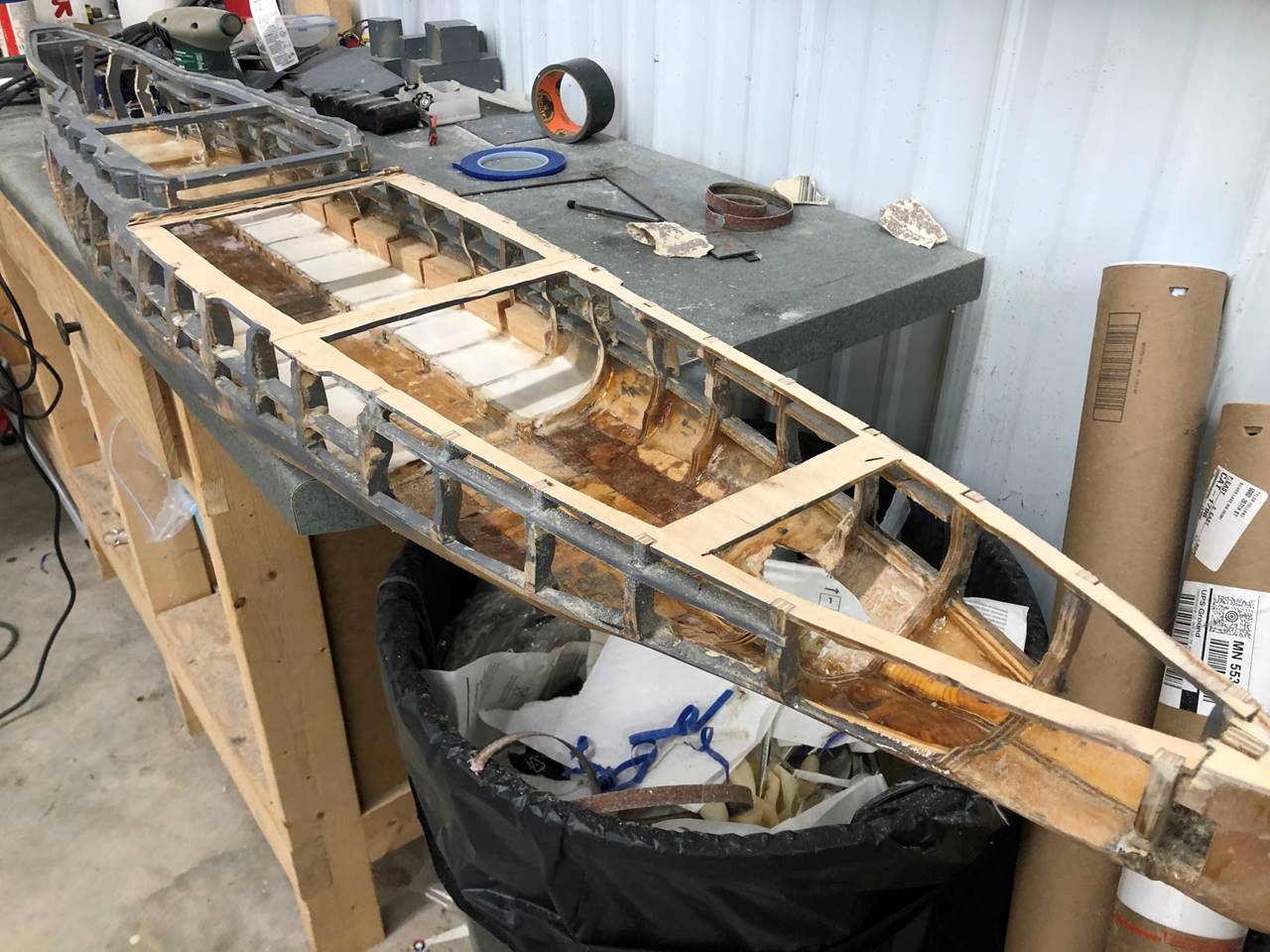
As I got to looking over the ship and imagining what
work needed to be done I started to make a mental list. When I received the
hull the bow sections of concrete sealer had already mostly been cut out
leaving the ribs and a small amount of concrete sealer behind, I prefer balsa
there so that would need to be cleaned up and new balsa cut and sanded and
sealed which is actually pretty easy. The rudder posts and dummy shafts were in
but the drive shafts had already been removed and the stern was partially
worked on, I ultimately opted to cut out the dummy shafts as the whole back end
needed to be redone any way. Also I only had 2 of the deck sections so at the
minimum I will need to replace the missing ones but it was sort of set up to
have as many as 5 removable sections, I prefer 3 at most so was planning on
changing how that comes together. The very bow of the ship can probably be
completely sealed from the top and not removable at all. The wood bulge
stringer had been partly removed on the port side, I planned to remove it all
and replace the wood with aluminum, and would want to do the same for the
higher up stern most stringer. The forward most sub-casement deck level was not
continued to the next rib as allowable in our rules and the section under the
casements should only be 1/8 inch thick and was built up a bit too much so that
needs to be re-sanded. Also, I think the stern subdeck is too narrow which can
cause problems with deck seal if there isn’t enough overlap, so sanding down
and redoing the subdeck is also on the list, I can probably live with the bow
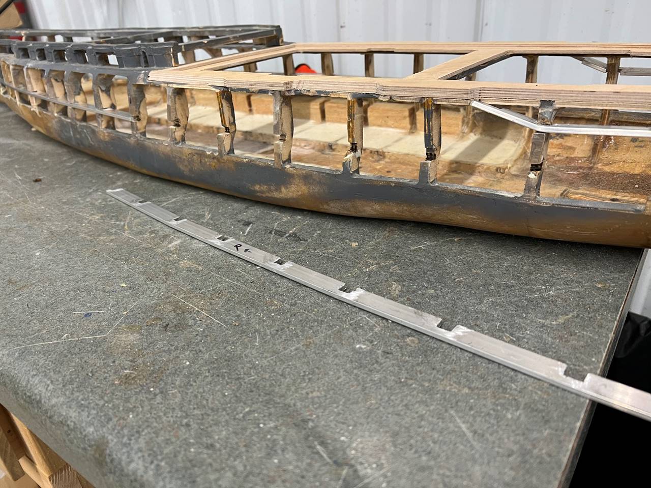
subdeck. Additionally though it is hard to see in this picture, there is bulge
water channeling made from the concrete sealer which I would usually do in
balsa and as such planned to rework.
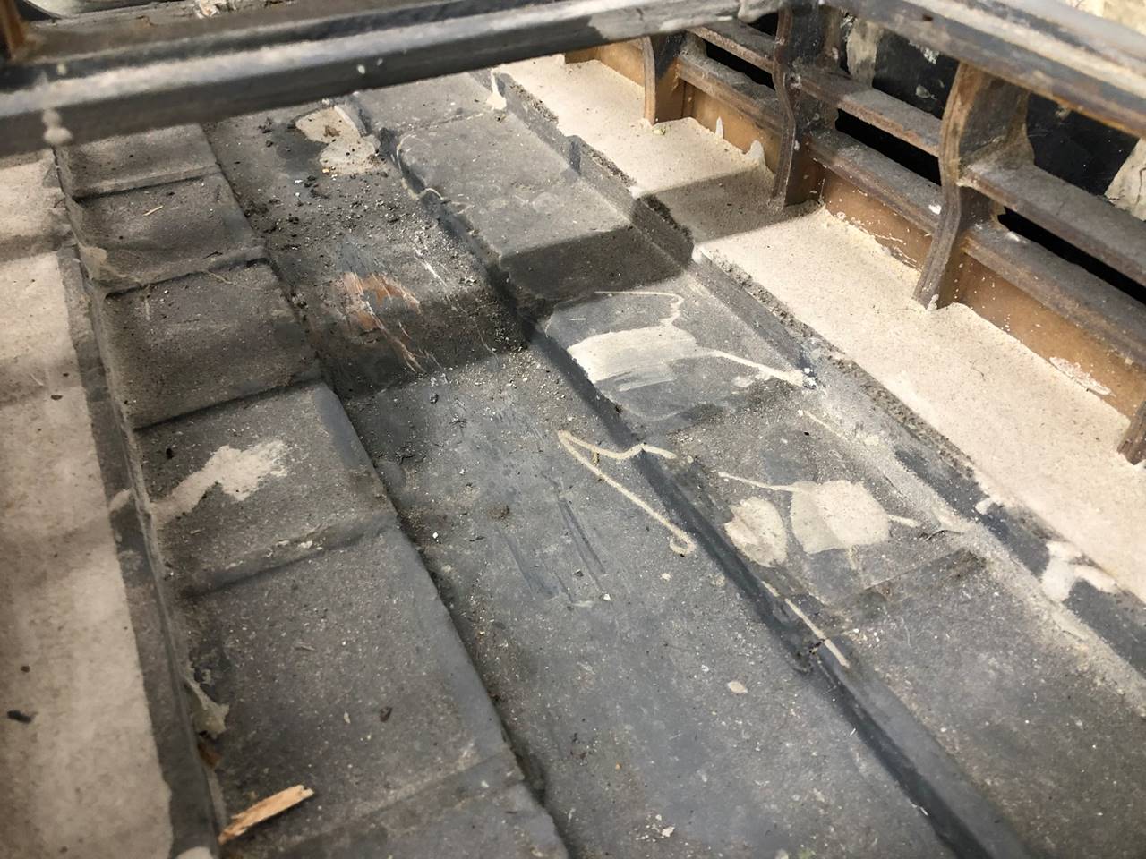
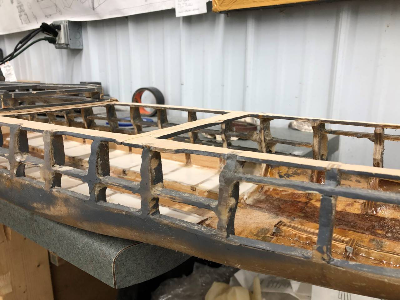
This is a fairly good look at the water channeling
amidships. The center of the ship has a water channel to allow water to flow
bow to stern under the other internal components, which is desirable. The next
level higher of darker gray you can see where the ribs naturally divide smaller
box like components where concrete sealer was filled, preferably this would be
a lighter material. The next level up/out is a lighter grey that is also
concrete sealer in the bulges, in my opinion it is also too heavy but also too
far towards the middle of the ship. Generally speaking, I like to be in more
control of ballast weight. I’d rather put lead along the outsides of the ship
and screw it down so the ship is more adaptable to future modifications. And
another principle of ship design that I like to keep in mind is that if you
have room for extra ballast weight it should be battery if possible, so it is
functional rather than dead weight. For these reasons I like to keep water
channeling material light. Another important principle is ship stability. Ships
perform better if the weight is as wide as possible along the bulges for the
width dimension, and as close to center as possible for the length dimension.
For these reasons fixed ballast in the form of water channeling is less
favorable to me.
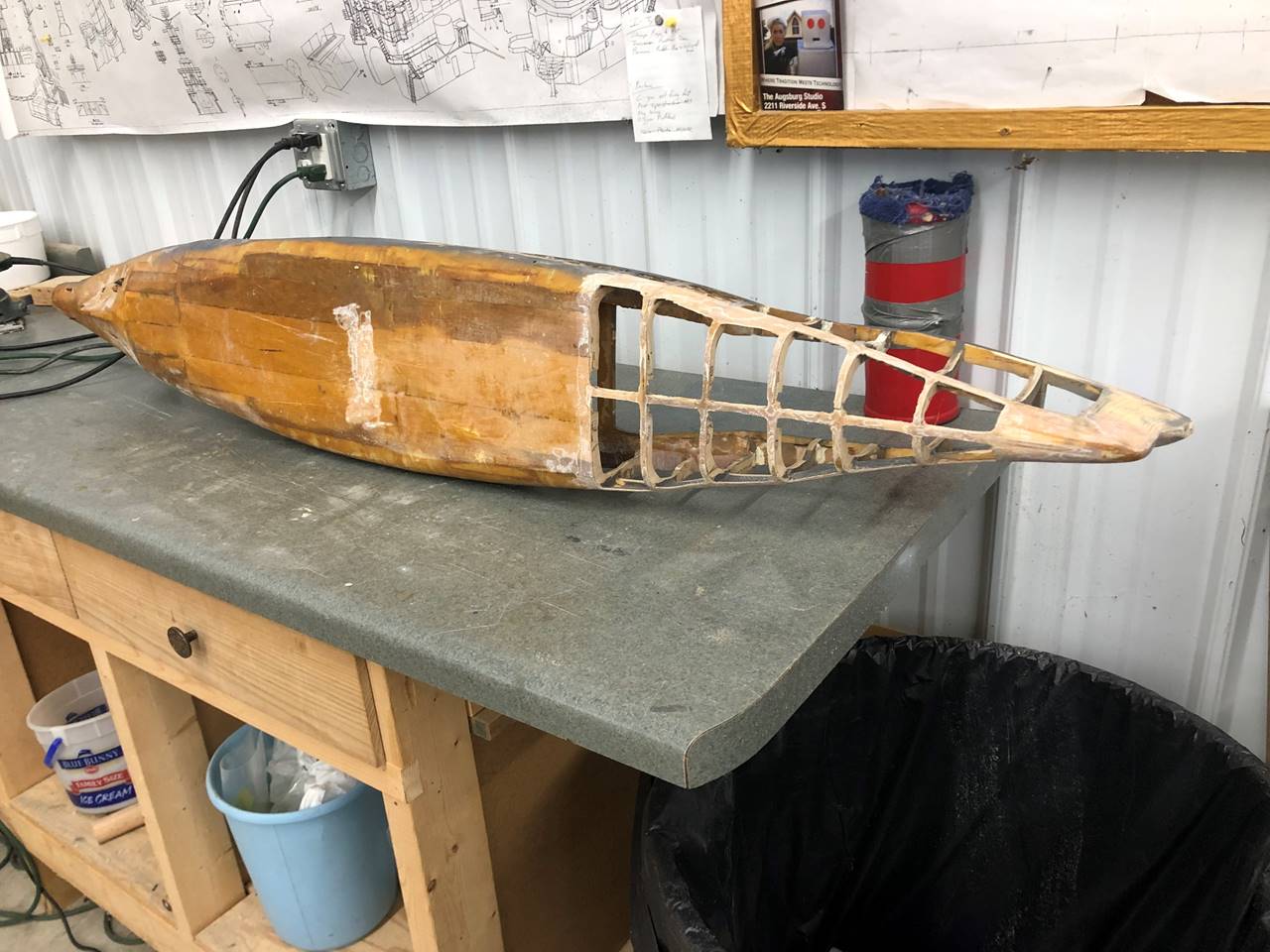
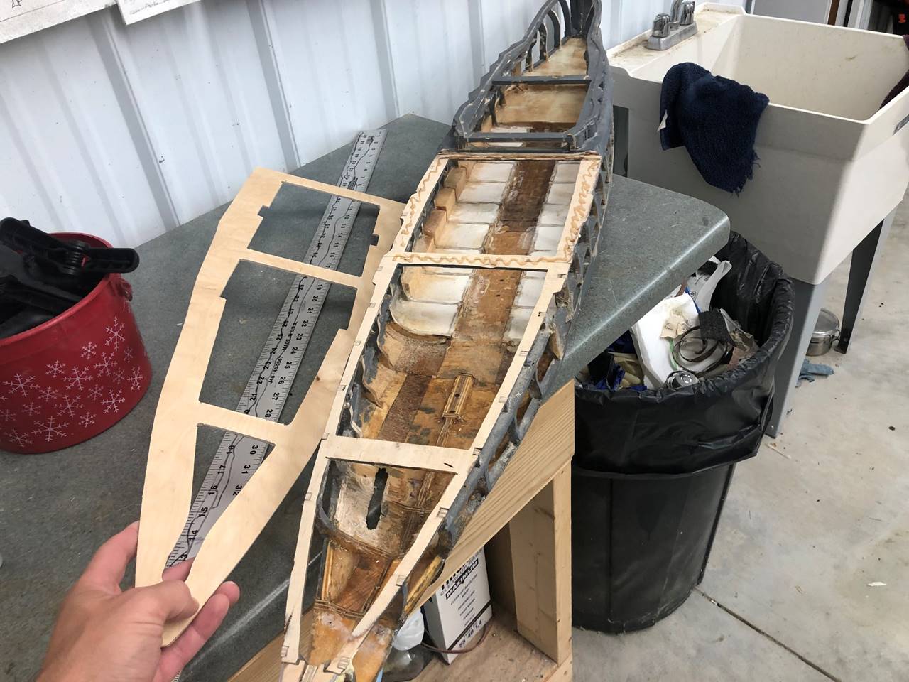
This picture was taken as the ship was getting closer
to being rid of the concrete sealer.
This picture shows how the concrete sealer was removed
from the entire ship down to the ribs and the wood layer that was placed on the
bottom of the ship. This process was extremely laborious. I used a combination
of Dremel cut off wheel/sander/routing bit as well as a hand held ½ inch belt
sander. It was very messy and I used the shop vac extensively as I was grinding
the probably toxic material out.
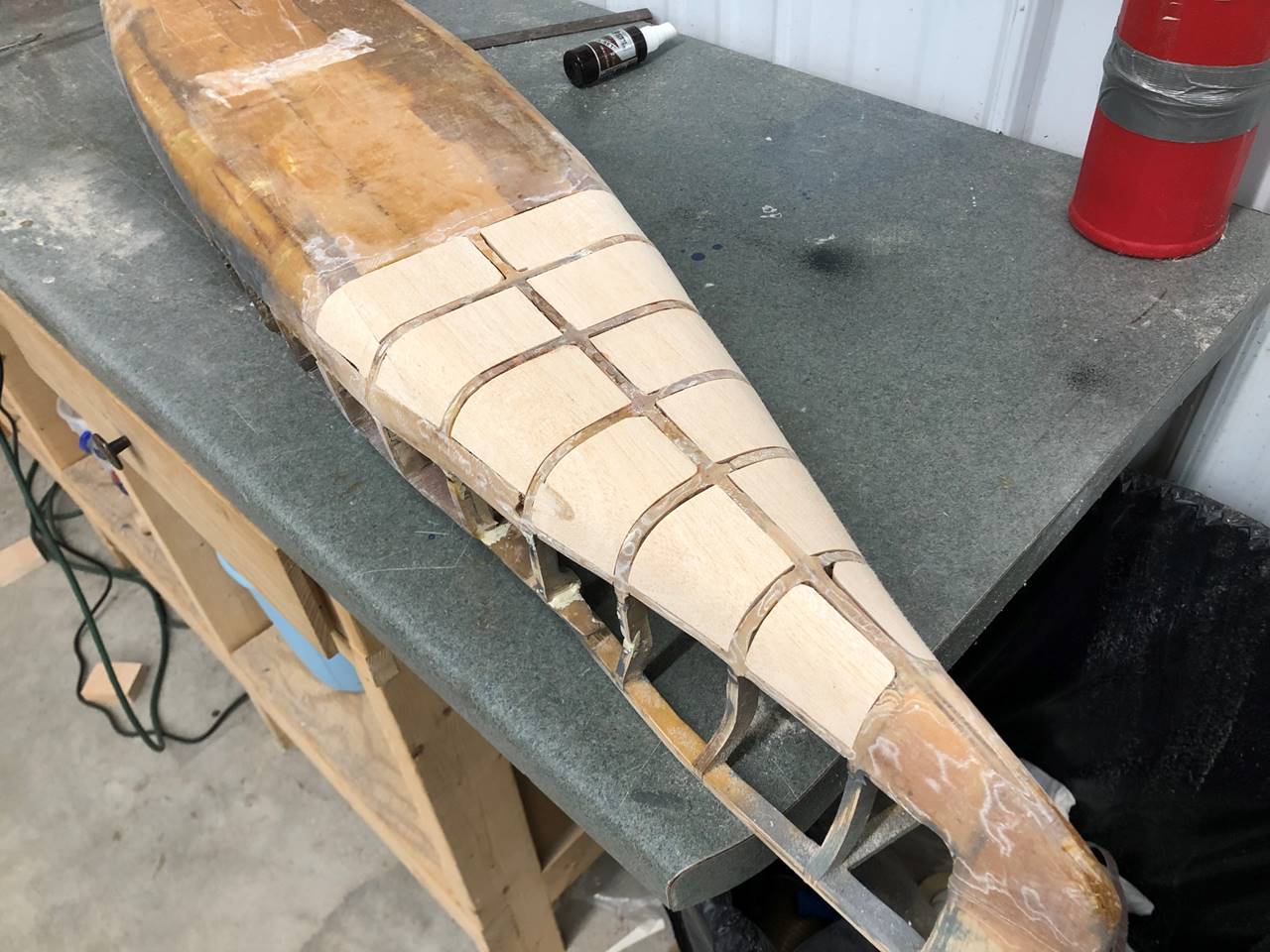
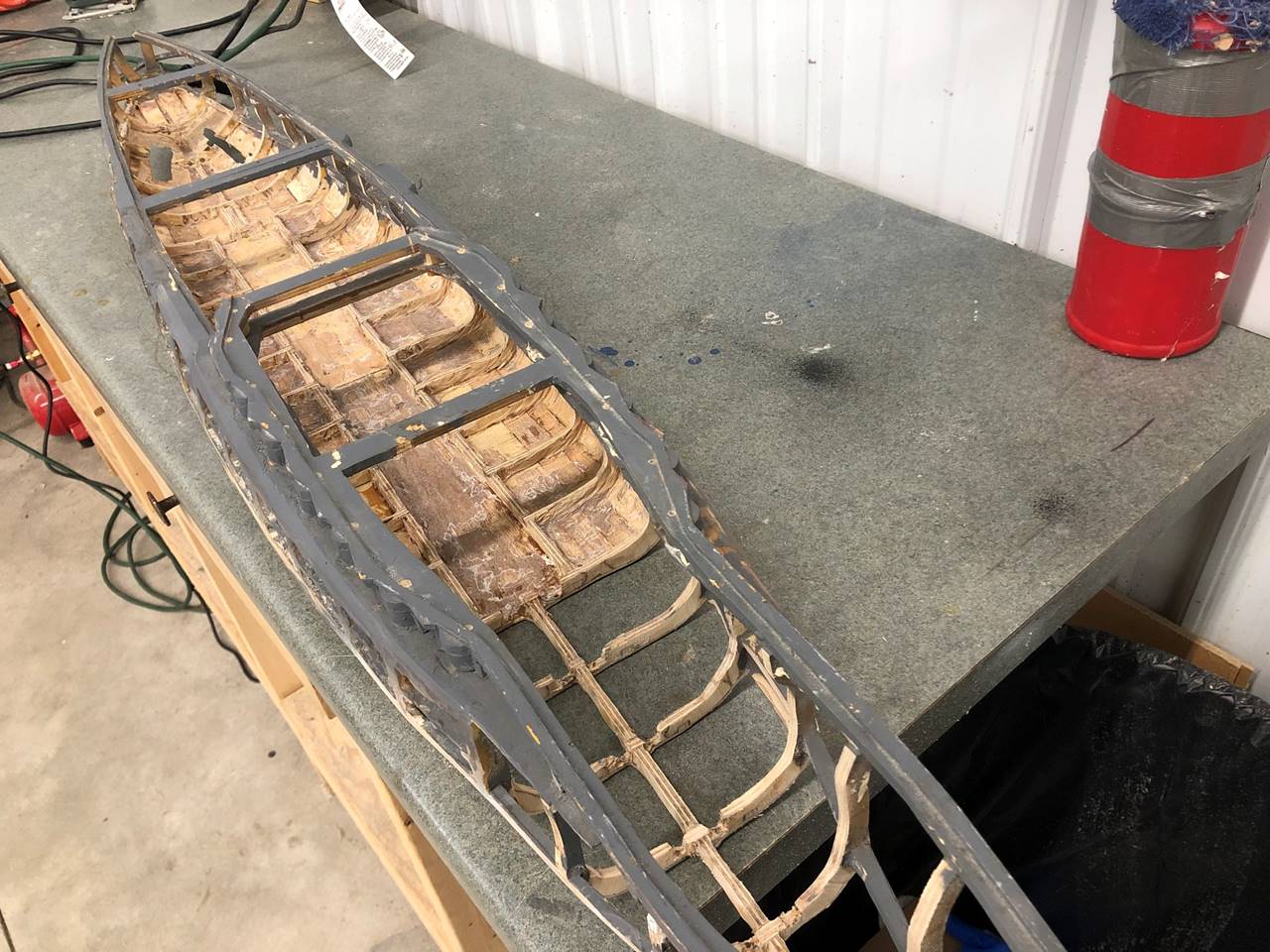
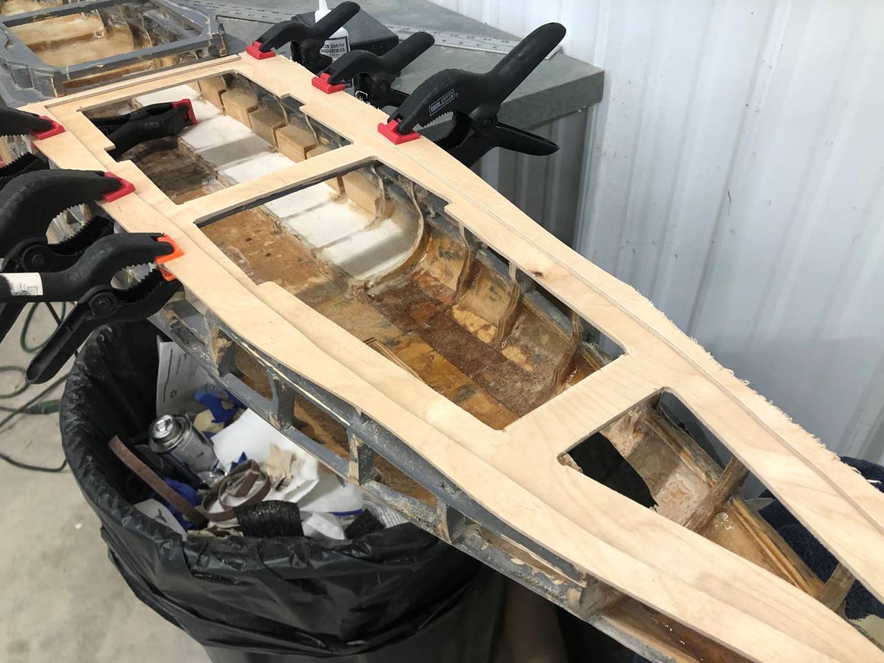
Here the balsa was cut to fit and glued in then sanded
to fit the shape of the left behind ribs.
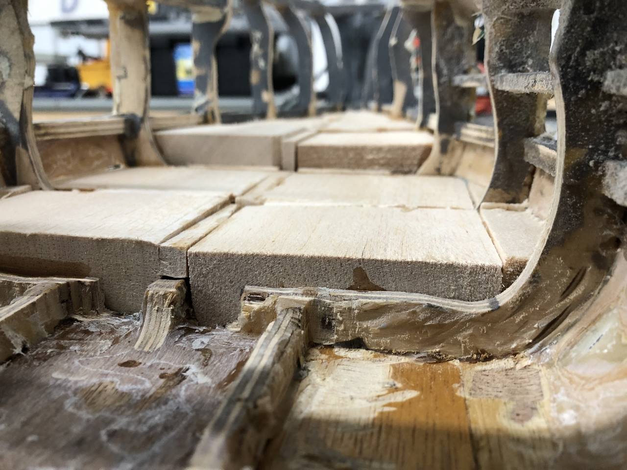
An angle from inside the boat shows how the balsa
blocks are fit to shape on the inside. The far bow was built up to ¼ below the
open window which was about 1.5 inches from the benchtop. The next level back
will probably hold the radio box so I didn’t want to build it up quite as high.
It is not quite 1 inch tall from the benchtop. Ultimately this will be filled
over with epoxy. I intentionally leave some small cracks at seams so the epoxy
will fill in all the spaces it needs to while it is liquid.
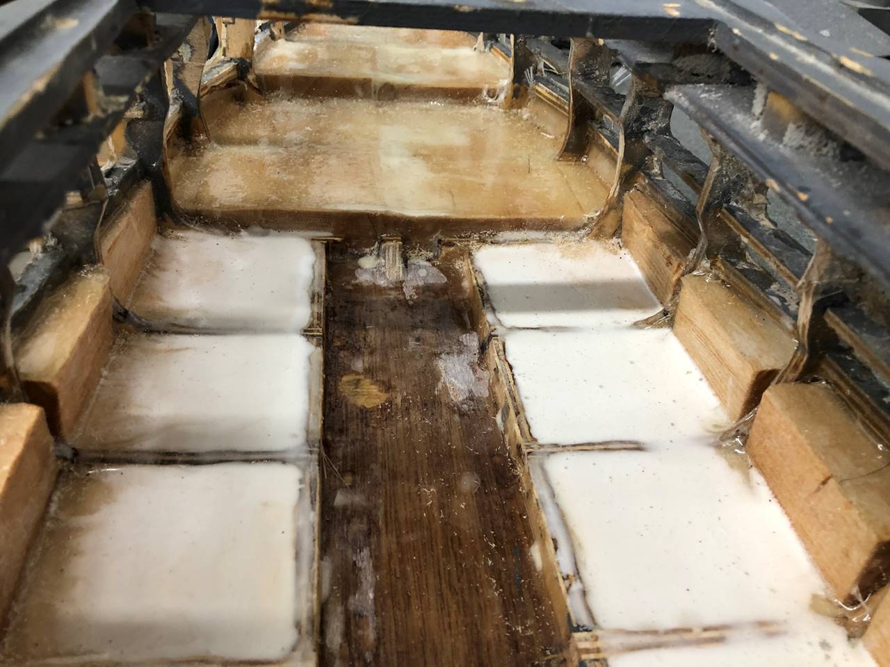
Here is the mid section
water channel and bow section is visible too. There is a white tint to the
epoxy because of micro-balloons. Fiberglass cloth is used over the balsa in the
bow so the incoming shots don’t do damage.
I was not happy with the amount of
deck rim in the stern part of the ship so I opted ot repace that whole section.
Most of the decks were not with the ship any way.
I sanded the top ¼ inch of the 3/8
inch deck/subdeck assembly leaving just a 1/8 inch thick portion.
The 3/8 became 1/8.
I then traced a new 1/8 inch thick
sub deck and glued it in.
I did the same for the deck that I
did with the sub deck. This is the rough cut and will be sanded smooth.
This picture shows the three sections
of 1/8 inch coming together, bottom was origional, middle is the new sub deck
with much wider overlap, and top is the new deck and deck rim. This picture
also shows how I use aluminum 1/8 inch stock to bend an armor belt into place.
This is pretty teadious but is very strong compared to wood.
The bow section was done a little
different. The need for a tight deck seal is not as great in the bow so I just
left the deck rim and cut new 1/8 inch decks to be inserted into the slots that
were already there. The far bow section in this ship will be permanantly glued
down as there is minimal need to access that space in a larger ship. The bow
most removable section will have the 2 bow turrets. The raised middle section
that sits under the superstructure will be one of the primary access points.
The stern most section will also be removable but generally need to be moved
less often. The midship stern section will also need to be routinely accessed
to change batteries/etc. I don’t usually like four sections and prefer 3 but
the central turrets and centrally located step leaves fewer options.
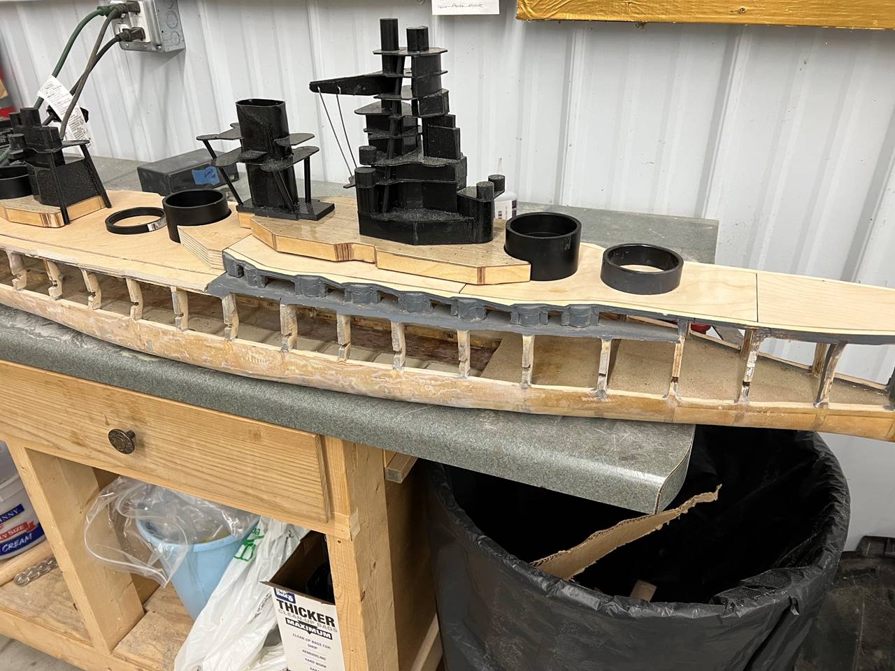
This is also a good look at the super
structure and barbet locations though the barbets are not the correct height in
this picture.
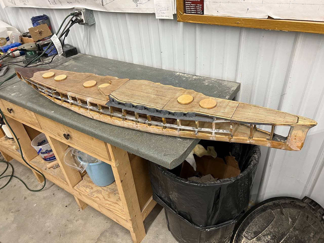
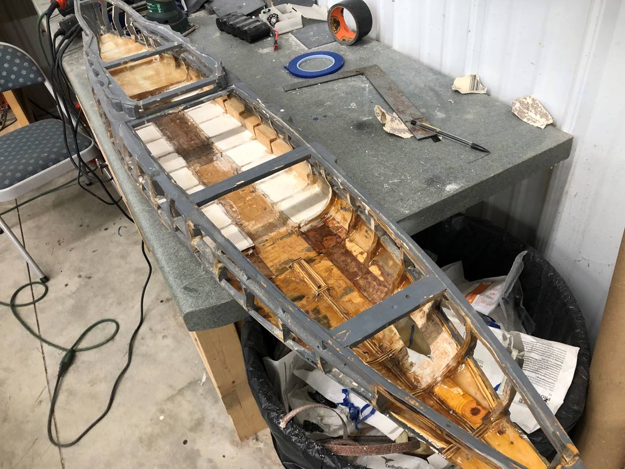
Stringers have been glued in and decks
are “planked” with pencil marks. The barbet holders are circular pieces of ¼ inch
thick plywood, the barbet is screwed latterally through into these pieces of
wood. I do this because the turets that contain the actual gun are higher off
the water and I don’t have to glue the entire barbet into the ship.
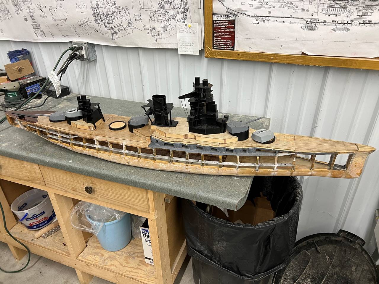
With the superstructure and turrets
in place it is starting to look like a real ship. I noticed I somehow am short
a turret. The plan at the time this picture is taken is to set her up with dual
sterns in the furthest back turret, stern sidemount in the 2nd to
stern turret and a stern sidemount in the elevated midships turret. It will
either have one or one and one half pumps, TBD. In this configuratou it should
be spaceous enough especially in the bow to have enough room for two pumps.