
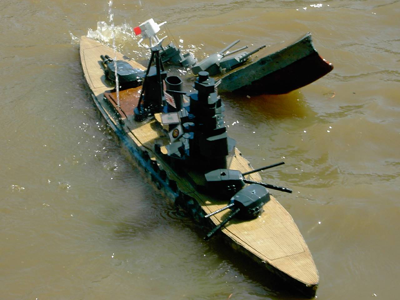
- INJ Nagato Build -
INJ Nagato – Tyler (launched 2010, major refit 2013)
6.0 units, 24 seconds, Japanese Battleship
Wood ships start as a set of plans that are developed into
ribs. Larger ships are probably better using a base board (in this case ¼ inch
ply wood) so that the water channeling can be directly cut out and incorporated
into the build from the early stages and it allows for a very solid foundation.
Some smaller ships like cruisers can be built upside down right onto the sub
deck and planked, later fiber glassing over it all. Just like with fiberglass
kits, a lot of factors contribute to where ribs should be placed – the bow and
the hull under the sidemoutns generally collect more
damage so more ribs can help keep some bb’s out, some hulls are very curvy and
need more ribs to hold odd shapes and curves, some hull features such as steps
and casemates allow for good areas to put ribs as well. Usually 4 inches apart is
about as maximally spaced as I would recommend and the rules dictate that they
can be no closer than 1 inch together. The number of ribs is generally 85% of
the total of the hull minus 2 inches in the bow and 1 in the stern, multiple
the remaining inches by 4 to get the number of ¼ inch ribs. For the Nagato I
weighted the density of ribs to favor the bow and under the sidemounts,
lined a few of them up to go along the casemates, and left the far stern
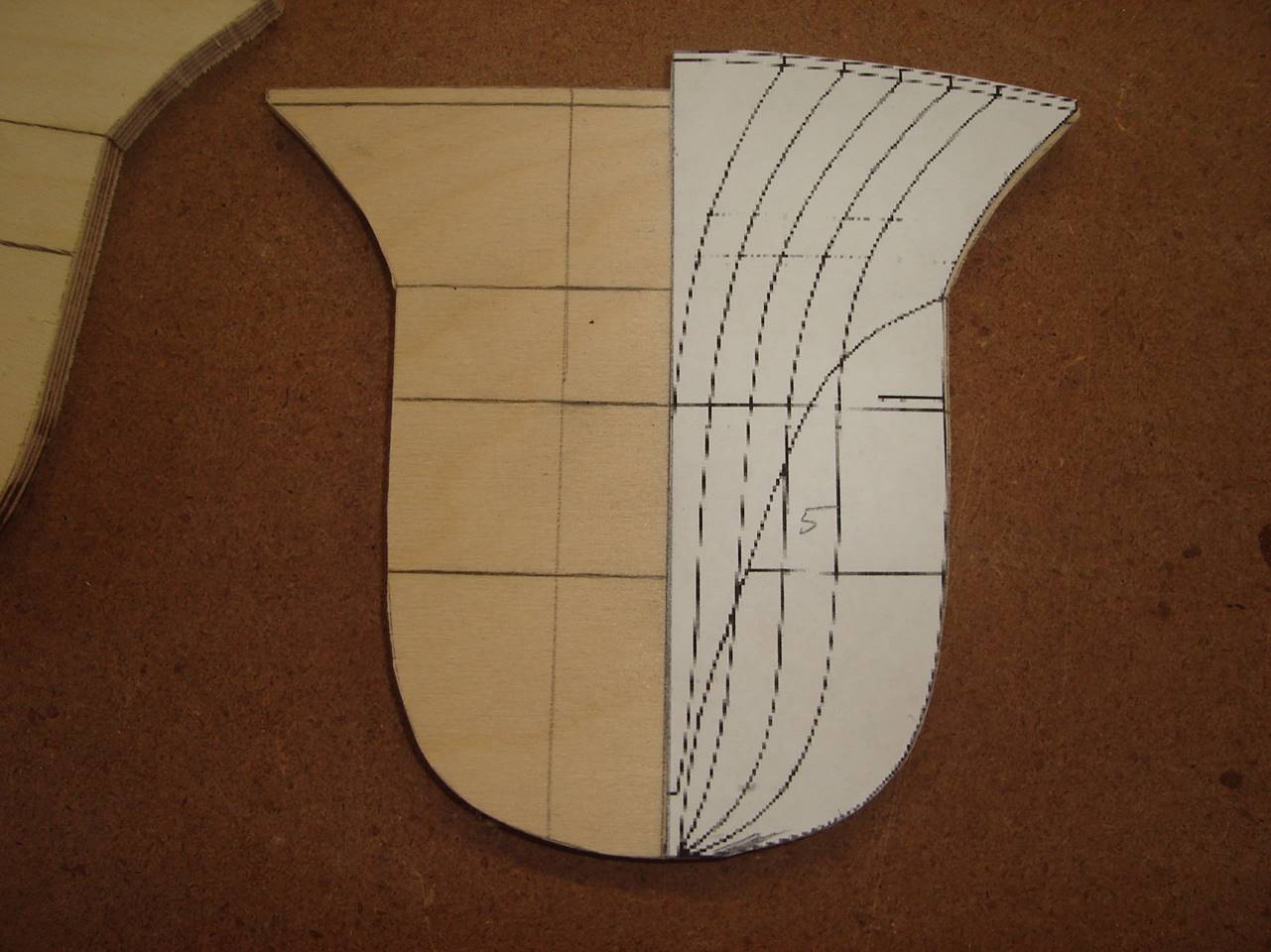
relatively open. Not every location that I wanted a rib had a rib on the hull
lines, so I had to make extrapolations. Most hull line sets come with just ½
the plan so I had to flip the pattern to get the other side. I’ve also done
this process digitally so that I have the whole rib on one piece of paper. Technology
is making it easier and cheaper to directly program and laser cut ribs and
decks as well. The ribs, subdeck, and base board are made from ¼ inch 5 ply
birch plywood. The deck itself is 1/8 inch 5 ply birch
plywood.
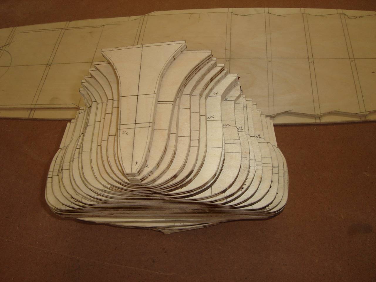
This is the full stack of ribs. I would advise marking
the waterline and the 1 inch below on every rib, the vertical centerline, as
well as the location of any other features such as stringers before gluing them
into the hull. I usually cut with a scroll saw and sand the edges to shape.
After they are glued in they will require a little
more sanding to make them all line up flush. Also the
middle of each rib needs to be cutout, with consideration of how thick the ribs
will be. 1 inch is plenty for most ships and 3/8 will suffice for most. Part of
the consideration is to make the ribs as thick as you want bulge water
channeling in the widest part of the ship. In the far bow and stern I fill in
the entire below the water line portion with balsa to act as water channeling.
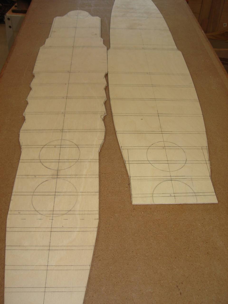
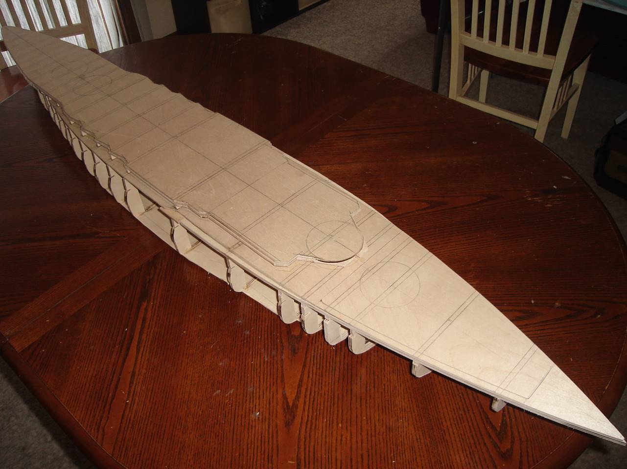
The decks are marked up with locations of ribs,
turrets, and the centerline. I would advise marking the underside like this,
not the top side unless you are planning on painting the deck. I realized my
mistake later on and erased and sanded the line I made.
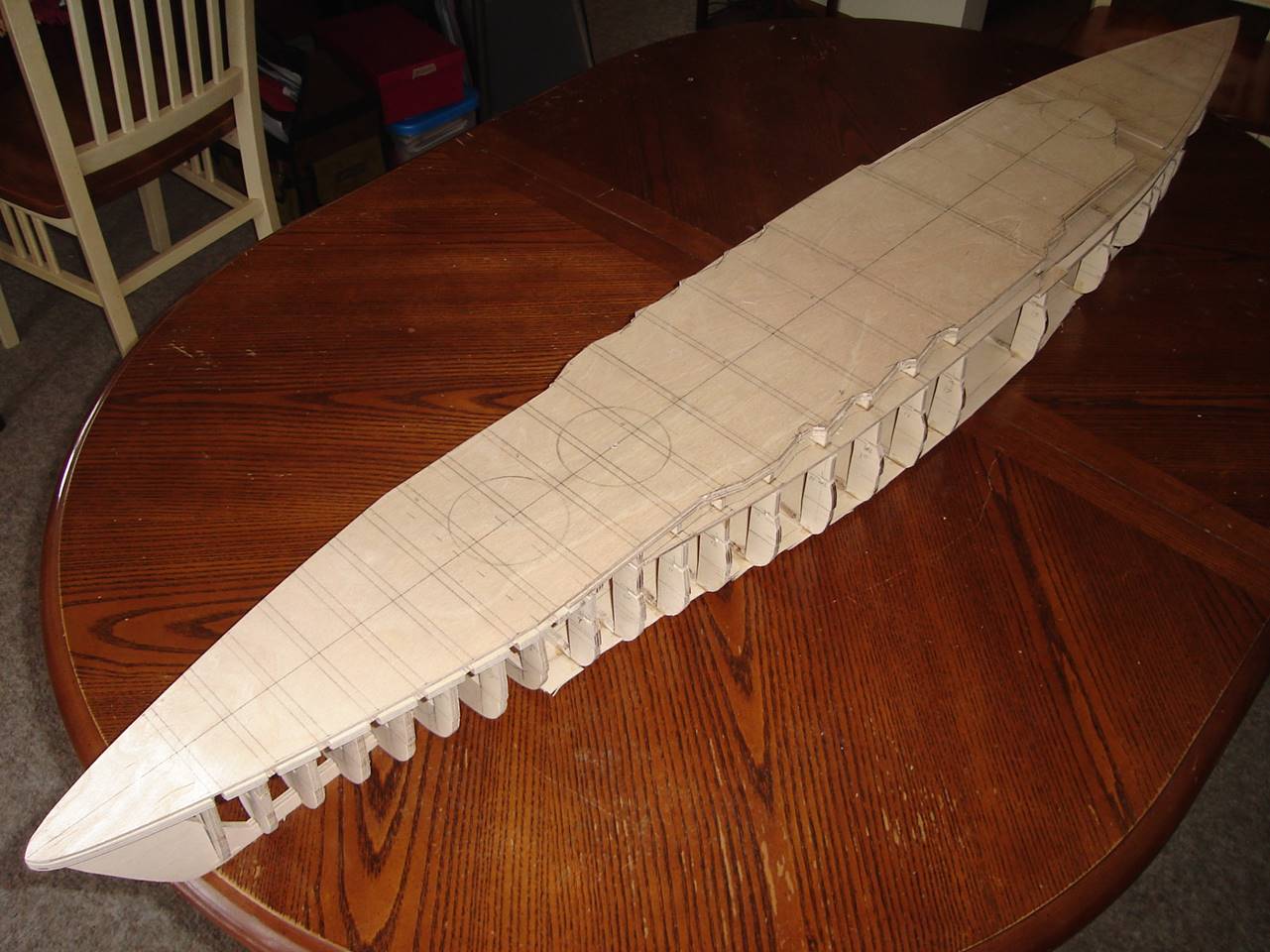
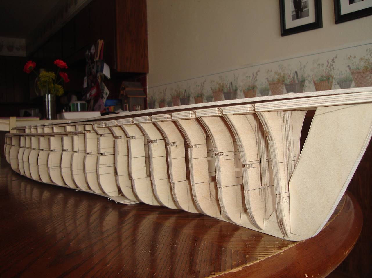
The ribs, deck, subdeck, keel in the bow, and base
board are all in place but the deck isn’t glued in yet. You can see there is
still sanding to do in the flare of the bow where the subdeck needs to be
sanded back.
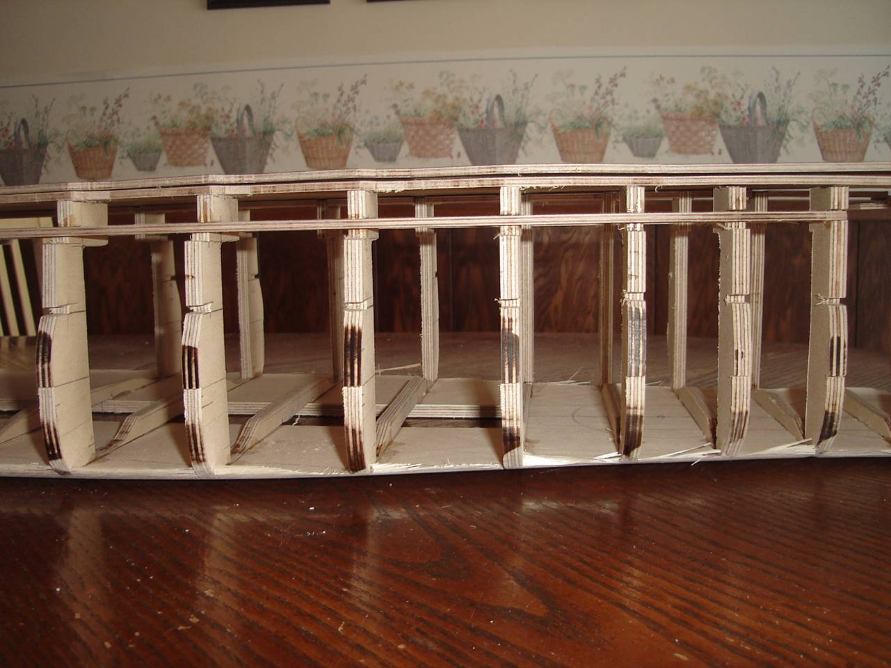
This pictures shows how the base board is cut to
accept the ribs. I will end up cutting out the center part of all of the ribs
in the middle section completely out and flush with the base board. You can
save yourself some time by thinning out the ribs to the point where they are
structurally sound but will come out easily with just a little more cutting or
sanding once everything is glued in place.
Along the length of the ship you can see where I left
notches to accept an aluminum 1/8 thick stringer. Also at the bottom of the
penetrable window I left a notch to allow for the thickening that happens after
adding the fiberglass and other impenetrable material so there doesn’t end up
being a bump in that part of the hull, this makes for more seamless sheeting. I
often run a keel in the far bow and stern to hold the shape as it comes
together. The gaps are filled with balsa. The for bow 2 inches I would
recommend plywood rather than balsa as it holds up better over time, this area
of the ship will be shot repeatedly.
The way the stern most deck was designed is a bit of a
flaw, I wanted the raised stern turret to stay solid with the hull but this
made accessibility very difficult. After a season or two of battling I cut the
stern deck further forward and placed a new stern deck in so that the stern two
turrets are on the same piece of deck section. The far stern is notable for
having very few ribs apart from right where the turrets are. This is a bit of a
weakness in design to some people, but the total area of penetrable hull back
here is minimal due to the curvature of the bottom side where the props and
rudders go. And generally you will collect very few bb holes in that part of
the ship.
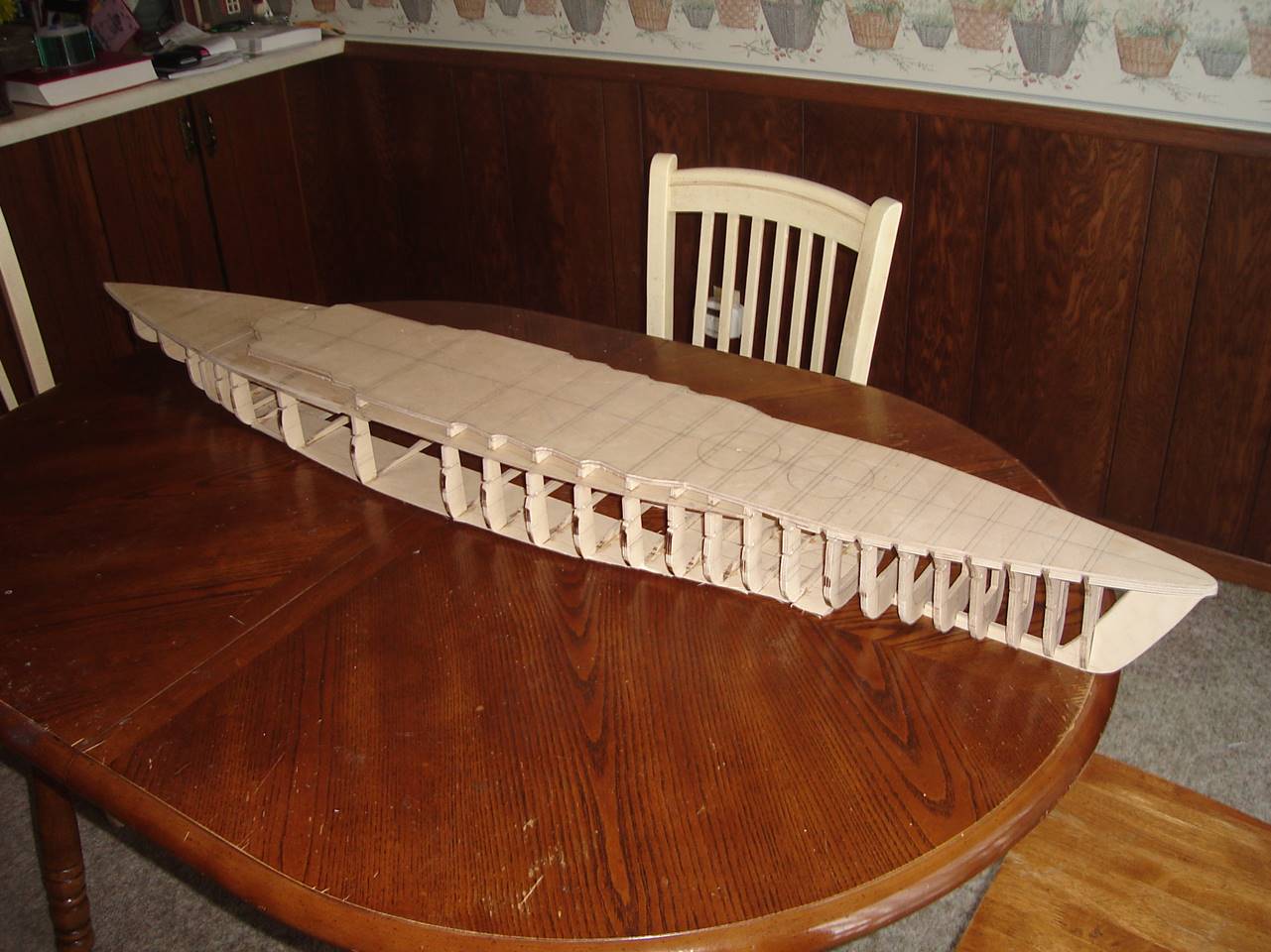
Another side profile shot.
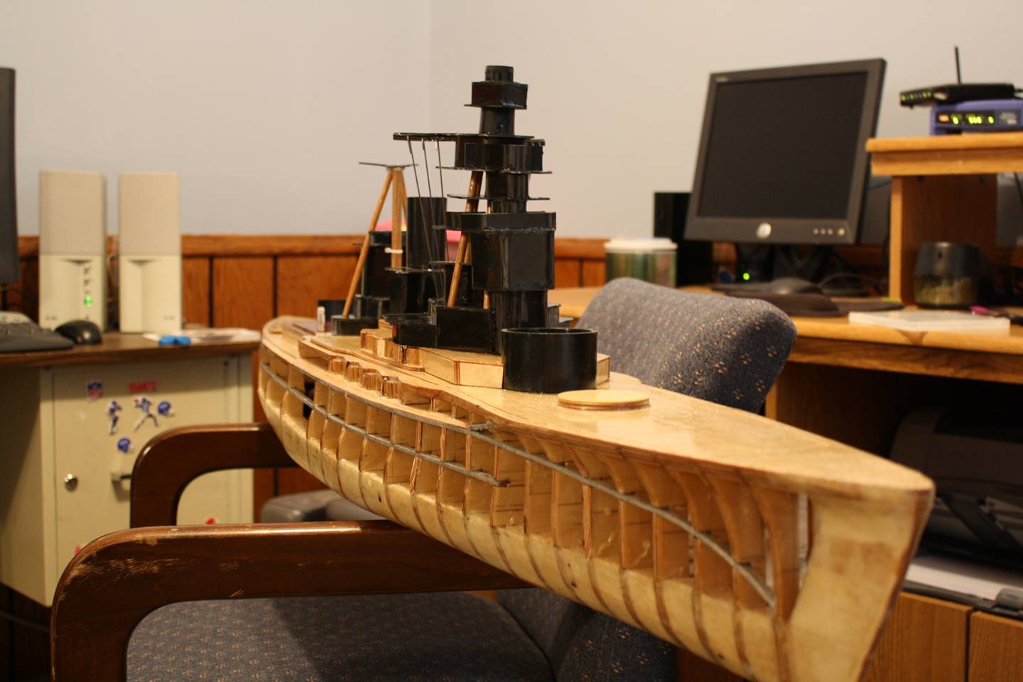
Evidently, I did a ton of work before taking another
picture. The super structure is mostly ABS because it is very strong and fairly
easy to work with, it sticks together well with ABS specific solvent/cement and
can be cut with just a score of the knife and a folded and snapped along the
score. The lowest superstructure deck is wood because I wanted the wood colored
deck in that section. The 1/8 inch aluminum rod stringers are fit into place
here. The bow forward of A turret is all filled in with balsa, as are the
widest part of the bulges amidships. All of the bottom of the ship is covered
with 3 layers of 5-6 oz fiberglass cloth with epoxy (the 2nd layer
is fit at a 45 degree angle for strength). The entire ship is covered with
epoxy for sealing and protecting the wood, the epoxy is essentially a layer of
plastic that can absorb some energy before the wood gets damaged. I have found
that every 5-10 years it should be sanded down and re-done depending on use.
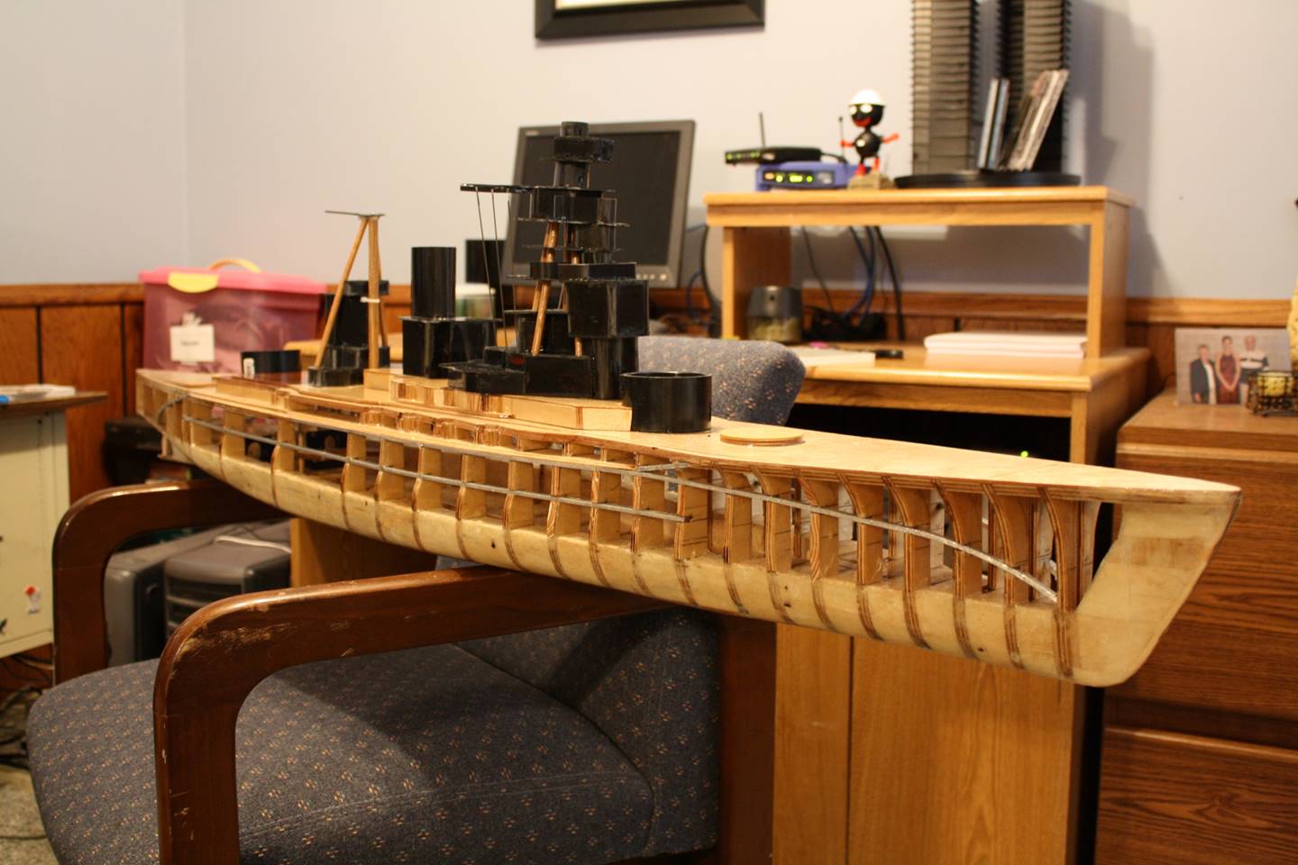
Side shot illustrates the same points as above.
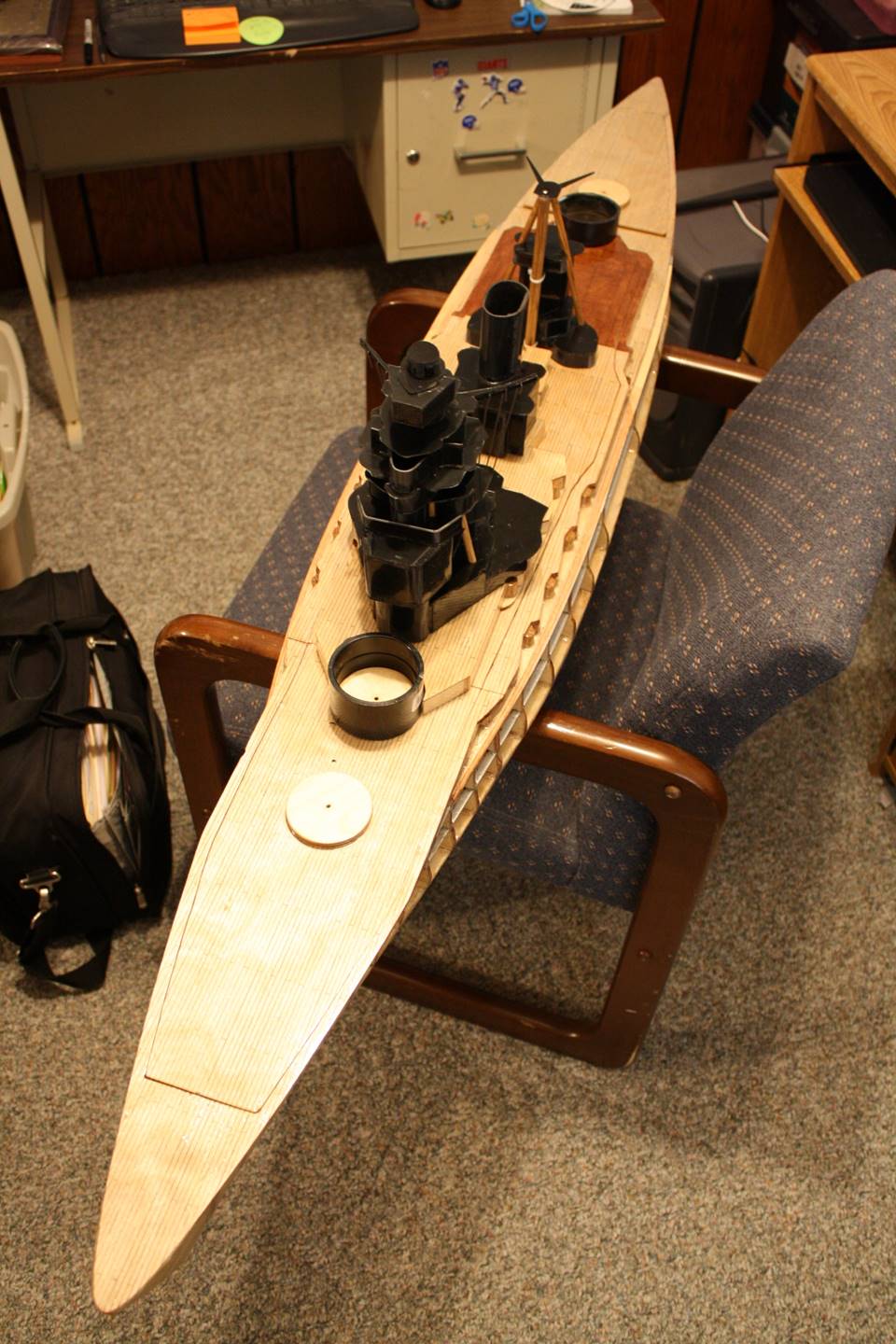
The overhead view shows how I draw lines on the deck
to look like little planks. Also you can appreciate how the decks slide apart.
The bow section contains the forward 2 turrets and is held in place with
latches and by the middle section. The middle section with the superstructure
is one piece that goes all the way back to the 3rd turret, this
slides in and locks with latches as well. The stern most section was built to
leave the 3rd turret as continuous with the hull but was
subsequently cut out to be removable with the stern most deck section. In
generally it makes transportation and general maintenance easier to be able to
take the superstructure off with a large chunk of deck in the center of the
ship and leave the sections with functioning guns alone.
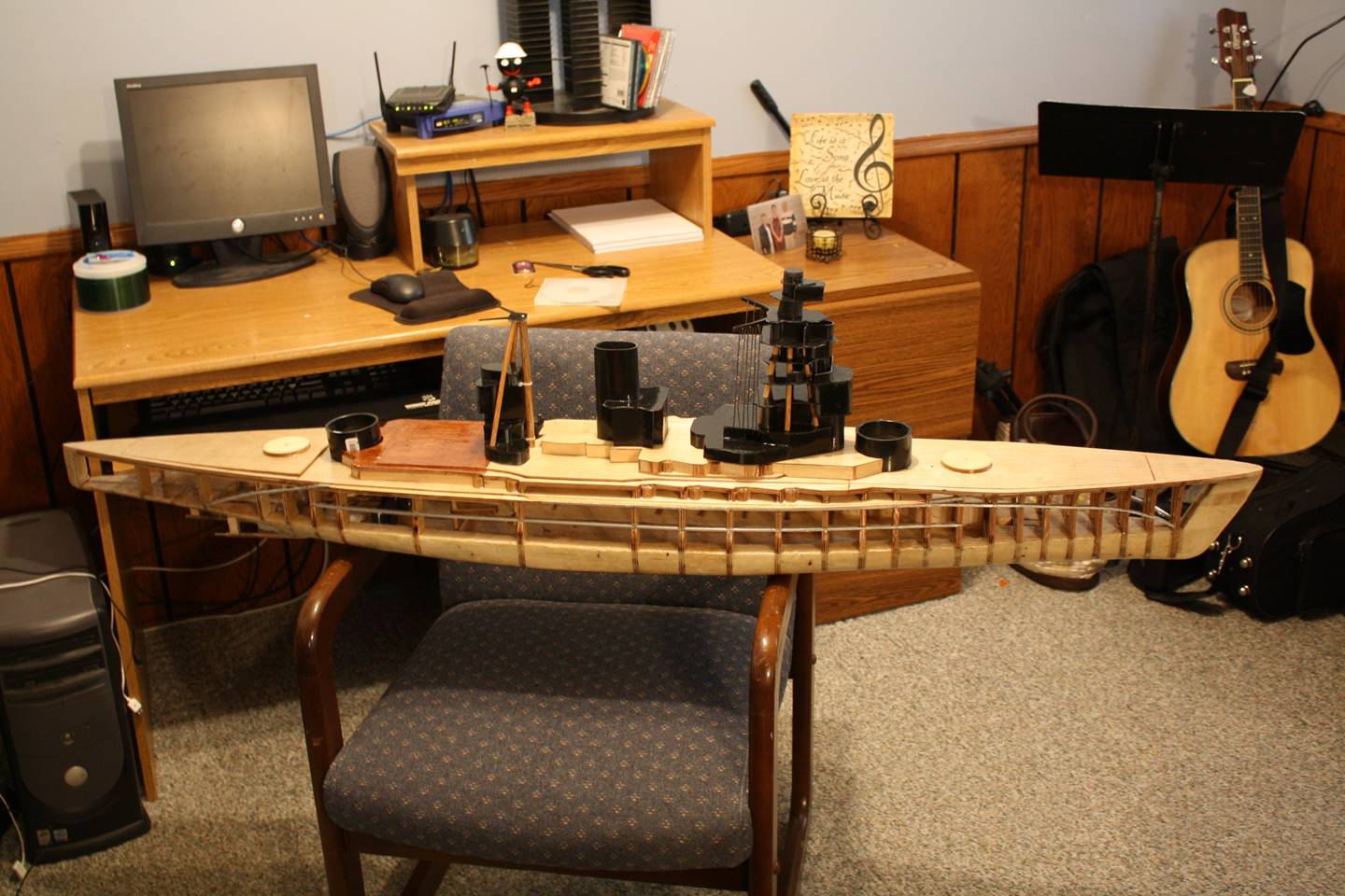
Side profile.
Bow section is seen with measuring tape. The original
cross brace made it very difficult to get the CO2 bottle in and out so it was
cut and a new one was placed right where the deck is cut behind the B turret.
The regulator is seen riding on top of the balsa block water channeling in the
extreme bow. The radio box is right behind the bottle. Later when this ship was
refit the bottle was moved to the center of the ship and the radio was moved
forward to sit under the bow two turrets.
The radio box though in a different location now is
essentially unchanged from the original build. You can see the mount for the
back of the bottle sitting right in front of the radio box, also the solenoids
are seen in front of that, they were screwed to a little piece of mounting ply
wood. In the middle part of the ship you can see the step down to the lowest
part of the cut out water channeling. This is just a very thin piece of ply
wood, I believe 1/32 that was countersunk into the bottom of the base board
before being fiber glassed over the bottom. The water channeling is generally 2
inches wide and runs from B turret to C turret, which is similar in most of my
ships.
Here you can see the pump mount and outlet. The
solenoid was zip tied to the pump mount. The drive motors sit behind the pump.
The rudder box can be seen here. This ship required a
fairly high torqe servo that didn’t come in a water
proof version at the time. I think I could find a water proof servo that would
do the job now but the rudder box is still in the ship as original. There are
two push arms that go to a large gear, the large gear turns the two rudders.
There are balloons that have silicone sealing to maintain both flexibility and
watertight integrity. Again you can see that the original deck was cut to keep
the C turret in place however you can also see that it is essentially
impossible to get to the gear boxes for the drive train and this was later
corrected.
T 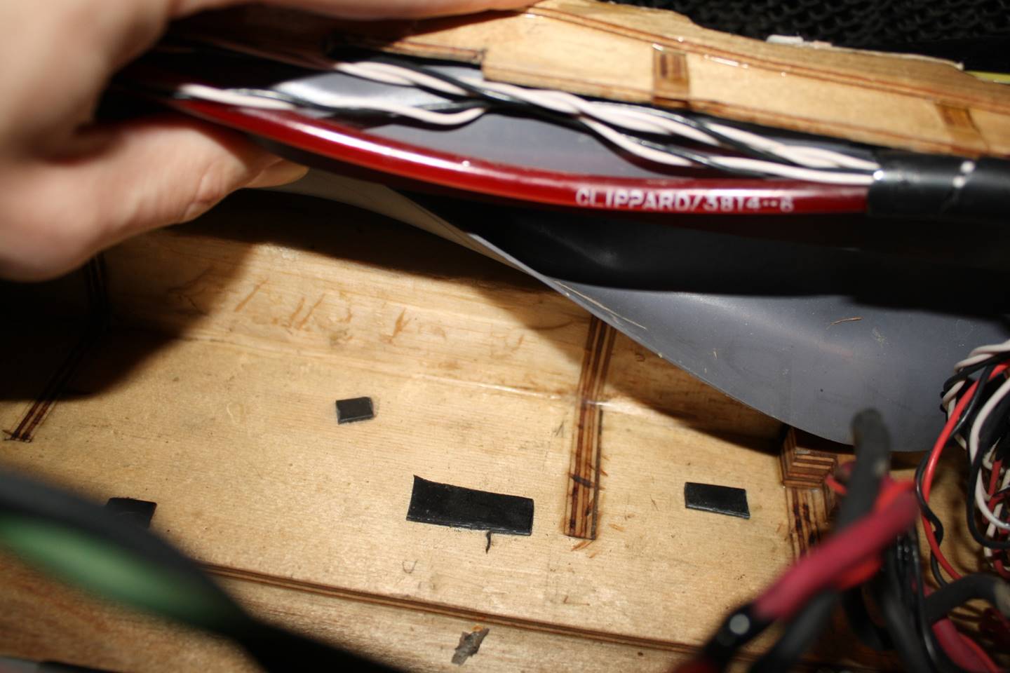
This is a midship section of the bulges, the balsa is
built up to the top of the water channeling and is about 1 inch or so wide. The
plastic rectangles were glued to the bottom to allow water to flow underneath
the original three 6 volt12 amp hour SLA bricks that powered the Nagato, but
still get the weight low in the ship. Without these water was trapping a bit
too much and the performance suffered as water wouldn’t flow very well to the
pump. A later refit changed to six 6 volt 10 amp hour NiMH batteries and the
plastic spacers were removed. The internal armor is shower pan liner and is
screwed to the wood ribs. I like to keep the wires and hosing out of the way by
running it along the outer edges of the top part of the interior, essentially
just below the subdeck when possible.
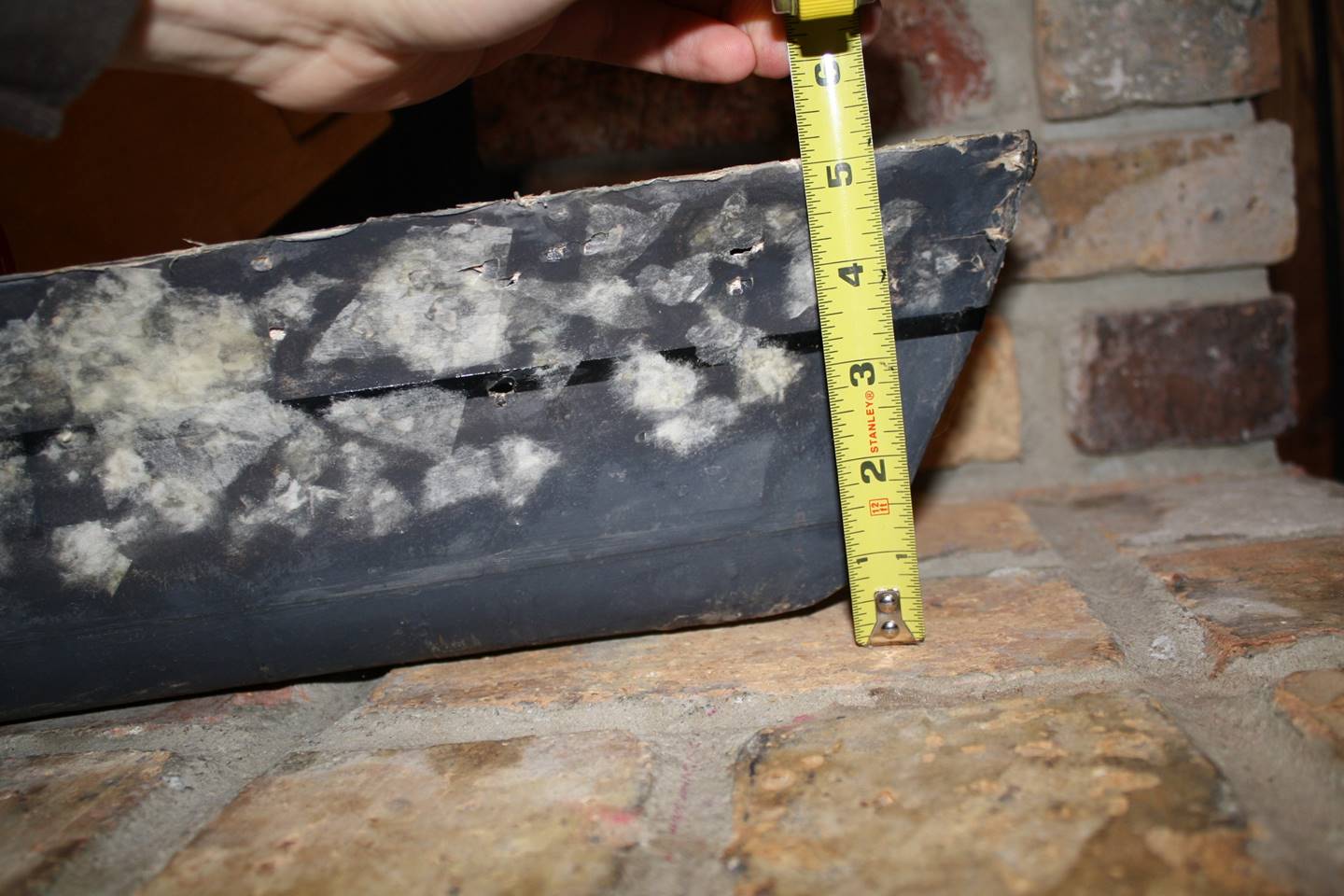
Height of the hull. I made the height as close to the
scale plans that I could, but at the end of the day are only as good as the
plan set.
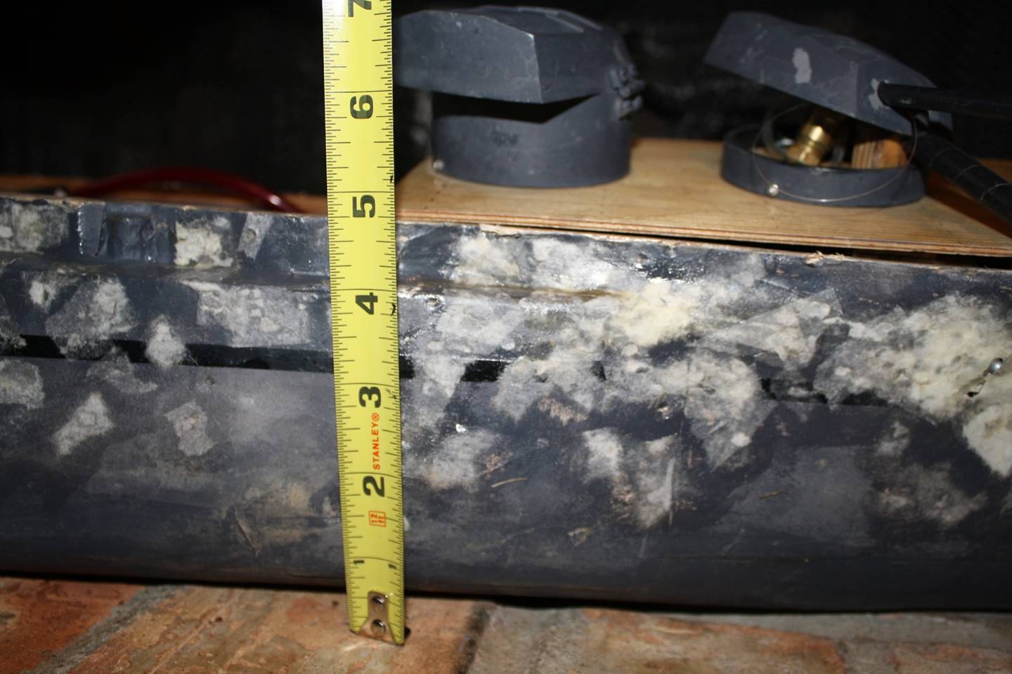
Height of hull in the casemate deck.
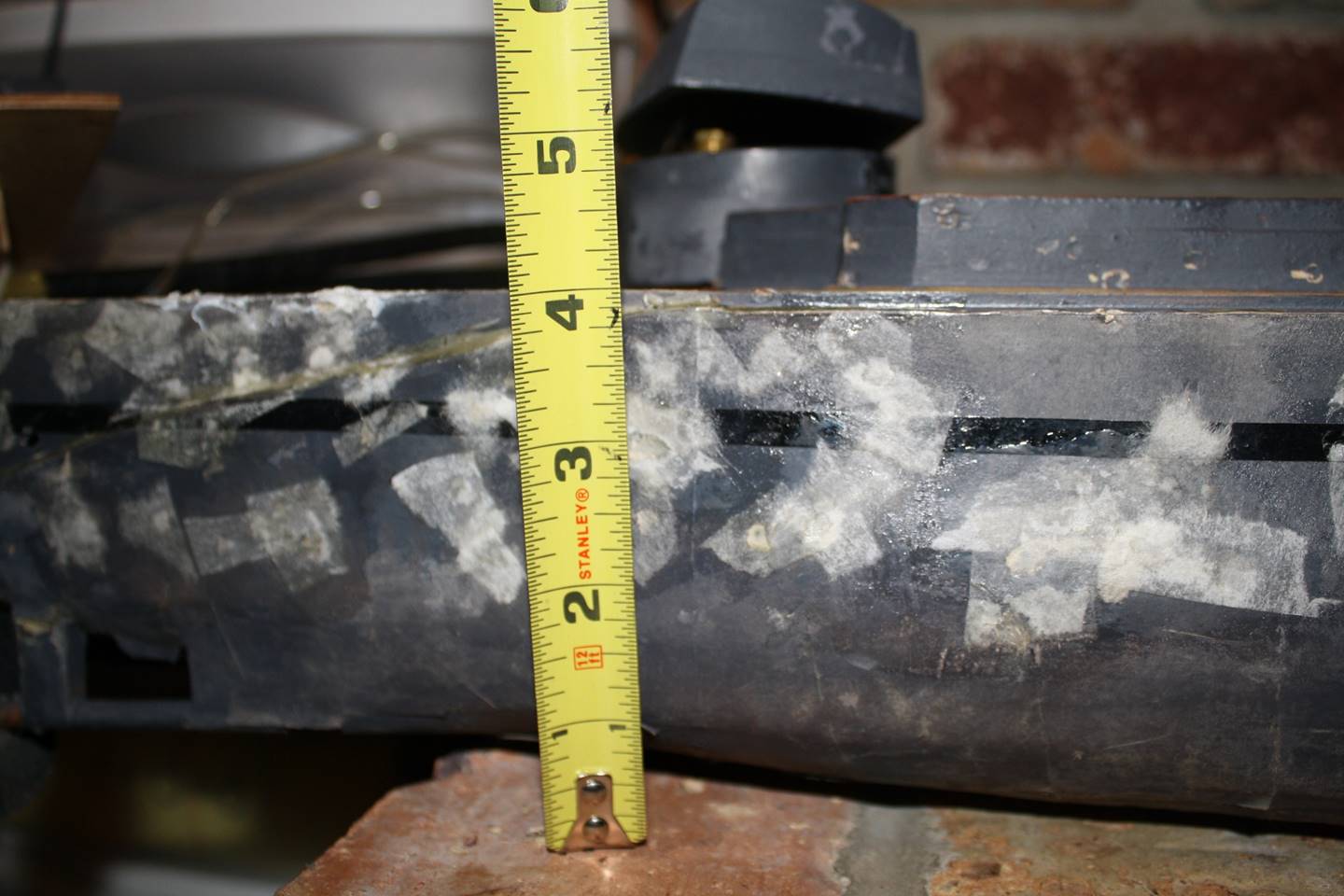
Height of the hull after the step.
As I’ve discussed above, the ship as-built had some
major flaws in terms of accessibility, battery technology, and battling
theory/gun setup. It was later converted to NiMH with 60 amp
hours rather than the 36 of lead acid and the CO2 bottle was moved to
amidships. A second pump was added and one of the 5 guns was removed. To see
how the ship looks now see the Inside
the IJN Nagato article.